

Automatic Voltage Controller
Key words:
Active voltage conditioner
Automatic voltage controller
Automatic voltage regulator
Classification:
Product Description
Voltage fluctuations can lead to unplanned production line shutdowns, causing the production line to operate abnormally and product quality to decline. It can also lead to serious consequences caused by production line disorder and disorderly start-up. In addition, the wear and tear on the machine is increased, which in turn shortens the service life and even damages the equipment. The Automatic Voltage Controller (AVC) developed by our company is an inverter-based system used to protect sensitive industrial and commercial loads from voltage fluctuations. This product can quickly and accurately compensate for voltage sags and swells, and can provide continuous voltage regulation and load voltage compensation functions. At the same time, the product has a power-off protection function, and the internal clock and user-set parameters are not affected by system power outages. The automatic voltage regulator is a three-phase five-wire single-phase compensation transformer-type voltage regulating output, which is suitable for situations where the voltage is unbalanced.
AVC Working Principle:
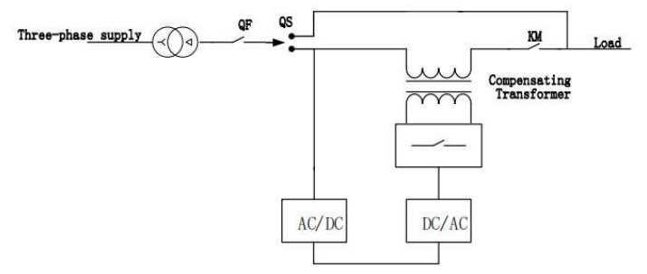
The automatic voltage regulator is composed of AC-AC converter, knife switch QS (interlock circuit breaker), molded case circuit breaker QF, contactor KM and compensation transformer. The AC-AC converter uses fully controlled power electronics to enable bidirectional energy flow. Knife switch QS (interlock circuit breaker) is used for maintenance and switches to the bypass state. Contactor KM is used to disconnect or connect the load in the compensation state. The automatic voltage regulator monitors whether the grid voltage deviates from the set value in real time by sampling the grid voltage. Once it deviates from the set value, it controls the AC-AC converter to output a voltage of the same polarity or opposite polarity to the grid voltage, and regulates the voltage in series. The voltage amplitude and polarity of the compensation transformer in the main circuit are adjusted to ensure that the load terminal voltage meets the set value.
AVC System Diagram

AVC Technical Specifications
|
Type |
Series 220V |
Series 380V |
|
Norminal Voltage |
AC220V (±20%) |
AC380V (±20%) |
|
Rated Frequency |
50Hz±5% |
|
|
Compensating Current |
30kVA |
30kVA, 45kVA, 60kVA, 80kVA, |
|
Network |
L/N |
3P4W |
|
Current Harmonic Distortion Rate |
Increment ≤1% |
|
|
Voltage Harmonic Distortion Rate |
Increment ≤1% |
|
|
Output Voltage |
220V±1% |
|
|
Voltage Regulating Way |
Stepless, Breakerless |
|
|
Regulating Way |
Separate phase regulation |
|
|
Power Factor |
0.5 lag to 0.7 lead |
|
|
Machine Efficiency |
≥95% |
|
|
SCR Bypass |
Yes, with Relay |
|
|
Display |
7-inch touch screen, providing parameter settings, power information |
|
|
Protection Function |
Input overvoltage/undervoltage protection, output |
|
|
Communication Methods |
Four-channel RS485 communication interface |
|
|
Altitude without Derating |
<2000m |
|
|
Temperature |
-20℃ ~ 50℃ |
|
|
Humidity |
<90% RH |
|
|
Pollution Level |
Below level Ⅲ |
|
|
Noise |
≤65dB |
|
|
Inlet Way |
Top entry |
|
|
Protection Grade |
IP20 |
|
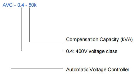
Code Rule:

AVC Product Parameters
|
Model |
Compensation |
System |
Size (W*D*H) |
Cooling Mode |
|
AVC-0.4-30k |
30 |
400 |
700*550*1200 |
Forced Air Cooling |
|
AVC-0.4-45k |
45 |
400 |
700*550*1200 |
Forced Air Cooling |
|
AVC-0.4-60k |
60 |
400 |
700*550*1200 |
Forced Air Cooling |
|
AVC-0.4-80k |
80 |
400 |
720*550*1200 |
Forced Air Cooling |
|
AVC-0.4- 100k |
100 |
400 |
720*550*1200 |
Forced Air Cooling |
|
AVC-0.4- 120k |
120 |
400 |
720*550*1200 |
Forced Air Cooling |
|
AVC-0.4-250k |
250 |
400 |
800*1000*2100 |
Forced Air Cooling |
|
AVC-0.4-500k |
500 |
400 |
1200*1000*2100 |
Forced Air Cooling |
Product inquiry
We will contact you within one working day. Please pay attention to your email.


